Setting On 555 Timer For Garage Door
Multisim Tutorial 4 555 Timer Astable Mode Simulation Youtube

Bike Turning Signal Indicator Circuit Using 555 Timer Circuit Turn Ons Circuit Diagram

Door Alarm Using 555 Timer Door Designs Plans Electronics Circuit Electronics Projects Electronic Schematics

555 Timer Time Delay Circuit Timer Circuit Electronics Circuit
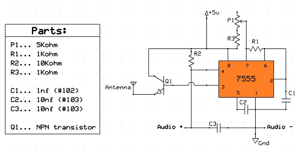
Am Radio Transmitter Using 555 Chip

Pin On Circuitos

After installation is completed place instructions in close proximity to garage door.
Setting on 555 timer for garage door.
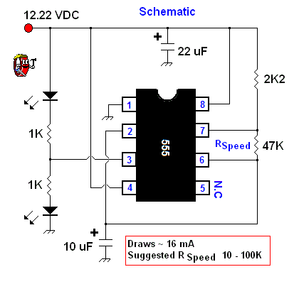
Timer Circuit Page 6 Meter Counter Circuits Next Gr

555 Timer Based Simple Electronic Code Lock Circuit Diagram Circuit Timer Electronics Circuit
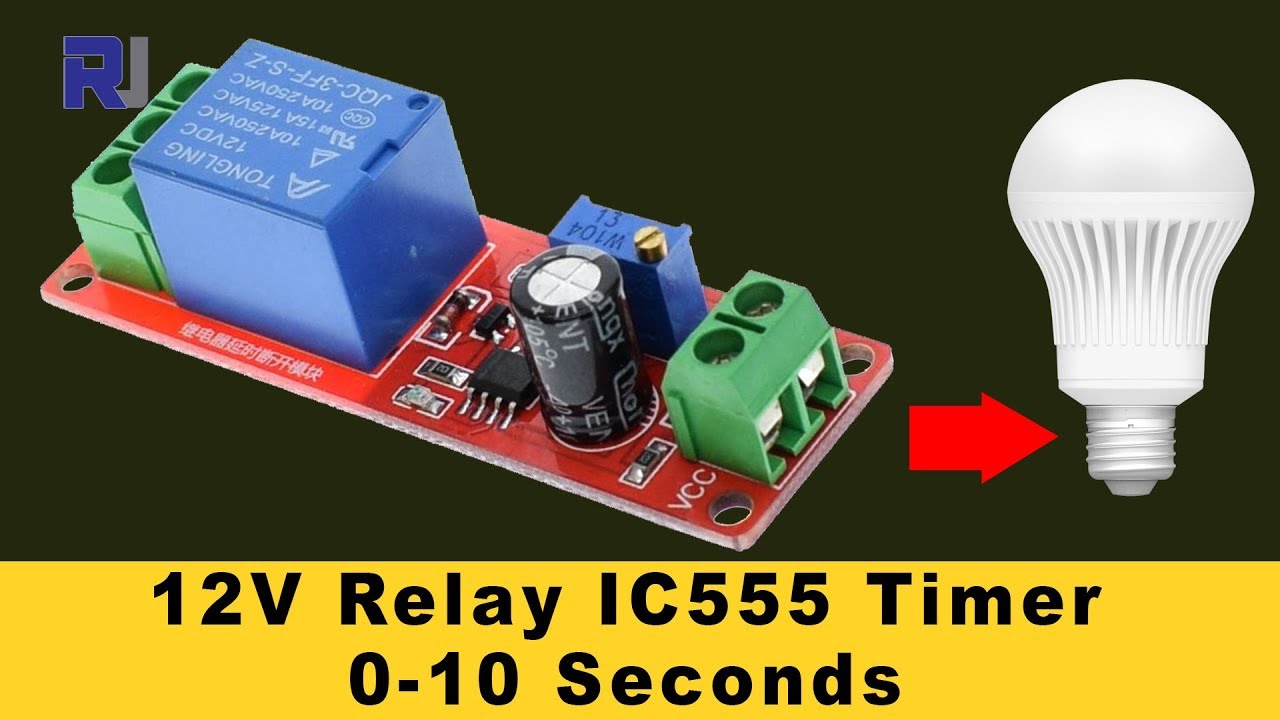
555 Timer Switch 12v Relay With Adjustable Time Test Review Youtube

Pin On Books Worth Reading
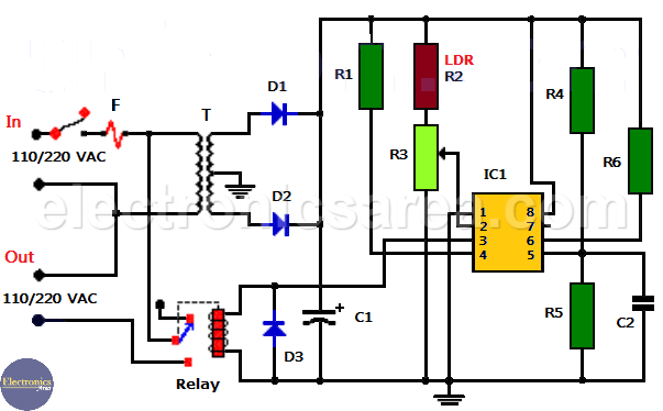
Automatic Night Light Using 555 And Relay Electronics Area

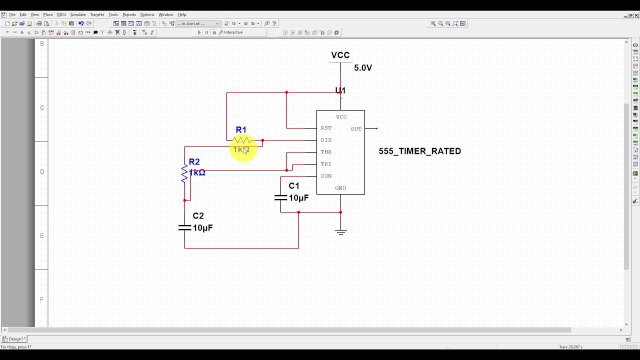
555 Timer Simulation In Proteus Youtube

Micro Inverter Schematic Diagram Google Search Teknologi

Diy Arduino Fingerprint Garage Door Opener Arduino Garage Door Opener Garage Doors

Pin On 555 Timer Circuits
Using Garage Door Safety Beams As Generic Photo Interrupter Sensors Casco Logix Garage Door Safety Garage Door Sensor Garage Doors

Pin On Electronic Circuit Diagrams

Voltage Controlled Oscillator Vco Circuit With A 555 Timer Voltage Controlled Oscillator Timer Synthesizer Diy

Unbiased Electronic Dice With Leds Using 555 Timer Electronic Dice Circuit Diagram Electronics

Stepper Motor Driver Using 555 Timer Circuit Diagram Stepper Motor Circuit Diagram Circuit
Source : pinterest.com
